
Step-by-step Installation of Smart BMS Monitored Mobile Power Container for Public Grids
Table of Contents
- The Grid Flexibility Gap: A Real-World Problem
- Why Mobile, Smart BESS Matters More Than Ever
- The Step-by-Step Installation: From Truck to Grid
- The Smart BMS: The Brain That Makes It All Work
- A Case in Point: Lessons from the Field
- Thinking Beyond the Installation
The Grid Flexibility Gap: A Real-World Problem
Honestly, if I had a dollar for every time a utility manager told me their grid was struggling with the renewable rollercoaster, I'd be writing this from a beach. We're all pushing for a cleaner grid - solar farms popping up, wind turbines spinning - but here's the on-the-ground truth nobody likes to talk about: the infrastructure to manage that variable power often lags years behind. The International Energy Agency (IEA) points out that grid flexibility is now the cornerstone of a secure energy transition. Yet, building permanent substation upgrades or large-scale BESS can be a regulatory and financial maze, taking 3-5 years minimum.
I've seen this firsthand. A utility needs to support a summer peak in one suburb, mitigate congestion on a specific line, or provide backup for a critical community facility during wildfire season. A permanent, fixed solution is overkill, too slow, and frankly, too capital-intensive for a transient, location-specific problem. This is the flexibility gap: needing megawatts of power, right here, right now, without a decade of commitment.
Why Mobile, Smart BESS Matters More Than Ever
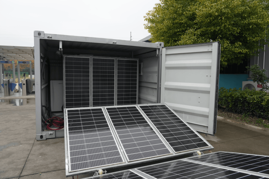
This is where the Step-by-step Installation of Smart BMS Monitored Mobile Power Container for Public Utility Grids shifts from a technical concept to a strategic lifesaver. Think of it as a "grid asset on wheels." It's not just a battery in a box. It's a fully integrated, UL 9540 and IEC 62619 compliant power plant that you can deploy in weeks, not years. The agility it offers is transformative. Need to reinforce the grid for a major sporting event? Deploy it. Need to defer a costly transformer upgrade by 18 months? Park it. It turns grid challenges from capital projects into operational maneuvers.
The Step-by-Step Installation: From Truck to Grid
Let's walk through what this actually looks like on site. This isn't theoretical; it's the distilled process from dozens of deployments.
Phase 1: Site Assessment & Preparation (The Foundation)
Before the container even leaves our facility, the real work begins. We conduct a rigorous site survey. This isn't just about finding a flat patch of gravel. We're analyzing:
- Geotechnical & Civil: Soil bearing capacity, drainage, and access road strength. You'd be surprised how many sites need minor reinforcement.
- Electrical Interconnection: Point of common coupling (PCC) voltage, available fault current, and protection coordination studies with the utility's engineering team. This is non-negotiable for safety.
- Environmental: Clearances, fire safety access, and noise considerations. We design for the local context.
Phase 2: Delivery & Positioning
The container arrives on a specialized trailer. With a qualified crane operator and rigging crew, we position it on pre-prepared foundations or pads. Precision here is key - a few inches off can complicate cable runs and maintenance access. We always use calibrated lifting equipment to avoid any torsional stress on the container frame.
Phase 3: Mechanical & Electrical Integration
This is where the hands-on integration happens:
- Anchoring & Grounding: The container is securely anchored to its foundation. A low-impedance grounding grid is installed and tested - this is your first line of defense for safety and system integrity.
- HVAC & Thermal Management Hookup: We connect the container's dedicated cooling system. Proper thermal management isn't about comfort; it's about battery longevity and preventing thermal runaway. We ensure ambient air intake and exhaust are unobstructed.
- AC/DC Cable Connection: Heavy-duty, correctly rated cables are run from the container's internal PCS (Power Conversion System) to the utility interconnection cabinet. Every termination is torqued to spec and visually inspected. This is a major source of field failures if done poorly.
Phase 4: Commissioning & Grid Synchronization
The most critical phase. We power up the system in a controlled sequence:
- Control Power & BMS Activation: Bring up the "brain" and monitoring systems first.
- Subsystem Checks: Verify HVAC, fire suppression, and internal communications.
- Functional Testing: Test all protection relays (over/under voltage, frequency, etc.) in isolation.
- Low-Power Testing: Synchronize with the grid at minimal power, test bidirectional flow.
- Ramp-Up & Acceptance Test: Gradually increase charge/discharge cycles to full rated capacity (the C-rate), validating performance against the contract specs. The utility's SCADA system is integrated, and setpoints are confirmed.
The Smart BMS: The Brain That Makes It All Work
Anyone can bolt batteries together. The magic - and the safety - is in the Smart Battery Management System (BMS). This isn't just a voltage monitor. A true Smart BMS, like the one we've refined at Highjoule, is a prognostic health monitor for every cell in the system.
It continuously tracks thousands of data points: individual cell voltage, temperature gradients, internal impedance, and historical charge/discharge patterns. Honestly, the goal is to catch a potential issue days before it becomes a problem. It allows for predictive maintenance, not just reactive alarms. This granular data is also what optimizes the system's Levelized Cost of Energy (LCOE). By perfectly balancing cells and preventing premature degradation, we extend the system's useful life and total energy throughput, driving down the real cost per megawatt-hour over the asset's lifetime.
A Case in Point: Lessons from the Field
Let me give you a real example. We worked with a municipal utility in the Midwest US facing a classic dilemma. A key 69kV transmission line needed reinforcement due to load growth from a new data center, but the upgrade was 24 months out. They faced potential congestion and reliability issues.
We deployed a 4 MWh Smart BMS-monitored mobile container adjacent to the substation. The step-by-step process was exactly as outlined. The challenge? A tight site with existing underground utilities and a need for minimal disruption. Our site prep was meticulous. The system was commissioned in under 8 weeks from contract signing.
The result? It provided targeted peak shaving and congestion relief for two full summers. The utility avoided potential violation penalties, maintained reliability, and bought the time needed for the permanent upgrade - all under a flexible service agreement. The Smart BMS data gave them unprecedented visibility into the asset's performance, building their internal confidence in storage technology.
Thinking Beyond the Installation
The final step in any installation is often overlooked: planning for the future. A mobile BESS is, by nature, an asset that may move. Our approach includes detailed decommissioning and re-deployment protocols. We document everything - cable lengths, grounding details, software configurations - so that when the grid's needs shift, the asset can seamlessly follow.
The question for any utility planner isn't just "Can this solve my problem today?" It's "Does this give me optionality and resilience for the unknowns of tomorrow?" A properly installed, intelligently monitored mobile power container does exactly that. It turns grid management from a rigid, long-term capital puzzle into a flexible, operational toolkit.
So, what's the one grid constraint keeping you up at night that a temporary megawatt boost could solve?
Tags: UL Standard BESS Smart BMS Grid Stability Mobile Energy Storage
Author
James Zhang
20+ years agricultural energy storage engineer / Highjoule CTO