
Step-by-step Installation of Tier 1 Battery Cell 1MWh Solar Storage for Public Utility Grids
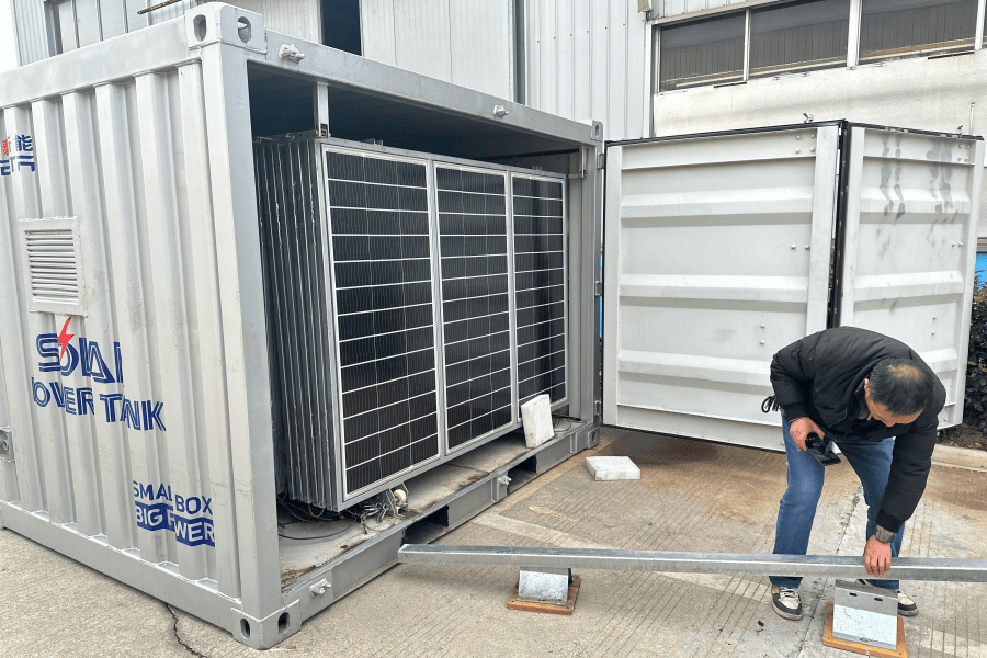
From Blueprint to Grid: The Real-World Guide to Installing a 1MWh Utility-Scale Battery
Honestly, if I had a dollar for every time a utility manager told me they were overwhelmed by the "how" of battery storage, I'd probably have retired by now. The vision is clear: integrate more solar, stabilize the grid, and future-proof your infrastructure. But the path from procuring those Tier 1 battery cells to having a fully operational, code-compliant 1MWh system feeding the public grid? That's where the real work - and the real value - lies. Let's talk about that step-by-step journey, the way we would on a project site.
Table of Contents
- The Grid's New Puzzle: More Solar, New Problems
- Why "Just Plug It In" Is a Multi-Million Dollar Mistake
- The Highjoule Blueprint: A Phased Approach to 1MWh Success
- Phase 1: The Foundation C More Than Just Concrete
- Phase 2: The Heart C Unpacking and Integrating Tier 1 Cells
- Phase 3: The Brain C Commissioning and Grid Handshake
- Beyond Installation: The Real Metric is LCOE
The Grid's New Puzzle: More Solar, New Problems
Here's the phenomenon we're all seeing from California to Germany: solar penetration is skyrocketing. The IEA reports that global renewable capacity additions jumped by almost 50% in 2023, with solar PV accounting for three-quarters of that growth. That's fantastic. But for public utility grids, this creates a familiar, sharp curve - the infamous "duck curve" - where net demand plummets during peak solar hours and then ramps up violently as the sun sets.
This isn't just a scheduling headache. It strains traditional peaker plants, creates voltage and frequency instability, and frankly, puts grid operators in a tough spot. The solution everyone points to is battery storage. But specifying a "1MWh system" is the easy part. The real question is: how do you install it correctly, safely, and in a way that it performs for its entire 15-20 year lifespan, under the watchful eyes of regulators and local fire marshals?
Why "Just Plug It In" Is a Multi-Million Dollar Mistake
Let me agitate that pain point a bit, based on what I've seen firsthand. A utility-scale battery isn't a server rack. You can't just pour a slab, drop a container, and flip a switch. The agitations are real:
- Safety & Liability: A poorly integrated thermal management system is a ticking clock. Local fire codes, especially under standards like UL 9540 and NFPA 855, are stringent for a reason. Non-compliance isn't an option.
- Hidden Costs: Think about interconnection studies, transformer sizing, and switchgear compatibility. Underestimating these can blow your budget. I've seen projects where the "balance of plant" costs nearly matched the battery hardware itself.
- Performance Gaps: Two systems with the same Tier 1 cells can have wildly different Levelized Cost of Storage (LCOS) based on installation quality. Poor cable management increases resistance. Inadequate spacing hinders cooling, forcing the system to derate itself on hot days - exactly when you need it most.
The data backs this up. A National Renewable Energy Laboratory (NREL) analysis consistently shows that project "soft costs" - engineering, permitting, interconnection - remain a significant barrier, sometimes up to 30% of total system cost for first-time deployers.
The Highjoule Blueprint: A Phased Approach to 1MWh Success
So, what's the solution? A meticulous, disciplined, step-by-step installation process that treats safety and performance as non-negotiable from day one. At Highjoule, this isn't just theory. It's the playbook we've refined over hundreds of MW deployed. Our approach is built on three core phases, each critical to turning a collection of premium cells into a grid asset.
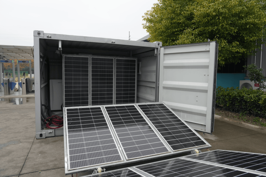
Phase 1: The Foundation C More Than Just Concrete
This phase starts long before the first truck arrives. It's about preparation and precision.
- Site Audit & Design Finalization: We're not just looking for flat land. We're analyzing soil reports for load-bearing capacity, checking drainage paths, and modeling sun exposure for thermal load. The container placement is optimized for maintenance access and safe egress routes, per local fire department requirements.
- Civil Works with Foresight: The concrete pad isn't just a slab. It includes precisely embedded conduit runs for power and data cables, grounding grid points, and often, secondary containment berms. Everything is documented against the approved site plan and IEC 62933 standards.
- Pre-Staging & Logistics: All major components - the battery container, power conversion system (PCS) skid, MV transformer - are scheduled to arrive just-in-sequence. There's no room for a $2 million transformer sitting in the weather for weeks. We also complete all local permitting inspections at this stage to avoid later delays.
Phase 2: The Heart C Unpacking and Integrating Tier 1 Cells
Now the core technology arrives. This is where deep product knowledge meets skilled fieldwork.
Step 1: Receiving & Verification. Each battery module (housing the Tier 1 cells) is inspected for shipping damage. We check serial numbers against manifests and verify the state of charge (SoC) as per the manufacturer's shipping specs - usually around 30-50%. This is crucial for safe handling.
Step 2: Mechanical Installation. Modules are carefully placed into their racks within the pre-fabricated, UL 9540-certified container. The torque on every busbar connection is precisely measured and logged. Why? A loose connection increases impedance, creates a hot spot, and becomes a failure point. This is a non-negotiable quality check.
Step 3: The "Central Nervous System" Hookup. This is critical. We install the Battery Management System (BMS) wiring, sensor networks (for voltage, temperature at each cell), and the thermal management system piping/cabling. The thermal system isn't an accessory; it's the lifeblood. We design for the local climate - active liquid cooling for Arizona deserts, perhaps a hybrid system for temperate Germany - to keep cells within their ideal 20-35C window. This directly preserves longevity and maintains the advertised C-rate (charge/discharge power) capability.
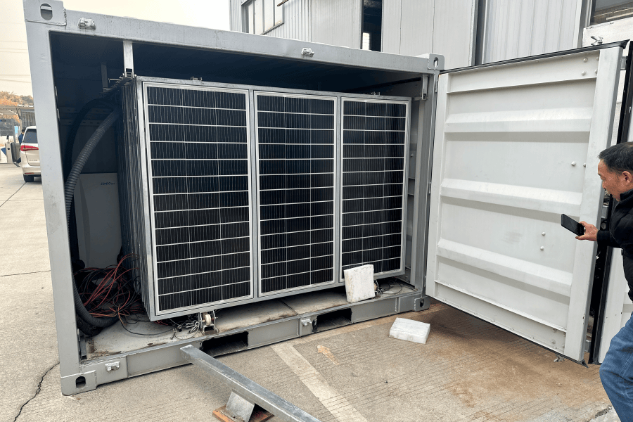
Phase 3: The Brain C Commissioning and Grid Handshake
With everything physically connected, we bring the system to life. This is a methodical, software-driven process.
- Pre-Commissioning Checks: Insulation resistance tests, high-potential (HiPot) tests on cables, and verification of all safety relays and disconnect functions. We ensure every alarm point - smoke, gas detection, temperature - talks to the central controller.
- Sequential Energization: We power up subsystems in a strict order: auxiliary loads, BMS, PCS, then finally, the DC battery string. It's done at low voltage, monitoring for any anomalies.
- Functional Performance Testing (FPT): This is the proof. We run the system through its paces: charge/discharge cycles at various C-rates, test the response to grid frequency signals (simulating frequency regulation), and verify the transition between grid-tied and islanded modes if it's part of the design. All data is recorded against the performance guarantees.
- Interconnection & Grid Acceptance: The final, formal step. We work with the utility's engineer to perform the interconnection tests, proving the system meets IEEE 1547 for grid support functions. Only after their sign-off do we close the switch for good.
Beyond Installation: The Real Metric is LCOE
Look, a successful installation isn't marked by a ribbon-cutting. It's marked by the system delivering predictable, low-cost energy for years. That's measured by Levelized Cost of Energy (LCOE). A proper step-by-step installation directly optimizes LCOE by:
| Installation Factor | Impact on LCOE |
|---|---|
| Proper Thermal Management | Reduces degradation, extends calendar life, maintains capacity. |
| Precision Electrical Work | Minimizes losses, improves round-trip efficiency. |
| Rigorous Commissioning | Catches early faults, prevents costly downtime later. |
| Full Standards Compliance (UL/IEC/IEEE) | Avoids retrofit costs, ensures insurance and operational approval. |
I remember a project in Northern Europe where our meticulous focus on the installation sequence and local grid code adaptation shaved weeks off the commissioning timeline. That meant revenue generation started sooner, which makes the CFO as happy as the grid operator.
The takeaway? The value of your 1MWh solar storage investment is fundamentally baked in during these step-by-step installation phases. Choosing a partner who lives and breathes this process - who brings not just Tier 1 hardware but Tier 1 field execution - isn't a procurement detail. It's the most critical project risk mitigation strategy you have.
What's the one grid constraint you're facing where a storage solution seems right, but the implementation path feels unclear?
Tags: UL Standard BESS Tier 1 Battery Grid Stability Solar Storage Utility Grid Energy Storage Installation
Author
James Zhang
20+ years agricultural energy storage engineer / Highjoule CTO