
Step-by-step Installation of Grid-forming Pre-integrated PV Container for EV Charging Stations
The Realist's Guide to Installing a Grid-Forming PV Container for Your EV Charging Hub
Honestly, if you're looking at scaling up EV charging capacity, you've probably felt the pinch. The grid connection quotes are staggering, the lead times are long, and the uncertainty around demand charges keeps you up at night. I've sat across the table from dozens of facility managers and developers in California and across the EU who share the same headache: how do you build a future-proof, resilient charging site without the grid upgrade becoming a project-killer?
That's where the concept of a grid-forming, pre-integrated solar and storage container comes in. It's not just another piece of hardware; it's a strategic asset. But here's the thing I've learned from 20+ years on site: a brilliant solution can turn into a nightmare with a messy installation. Today, let's walk through the step-by-step installation of a grid-forming pre-integrated PV container for EV charging stations. I'll share the pitfalls we've seen firsthand and how a methodical approach saves time, money, and a whole lot of stress.
Table of Contents
- The Real Problem: It's More Than Just "Plug and Play"
- Why "Pre-Integrated" is Your Secret Weapon
- The Installation Blueprint: A Step-by-Step Field Guide
- Beyond the Basics: The Expert Insights That Matter
- Your Next Step: Asking the Right Questions
The Real Problem: It's More Than Just "Plug and Play"
The dream is a turnkey system. The reality? I've seen projects where the BESS arrives, and the site team realizes the foundation isn't rated for the dynamic loads, or the local inspector has a completely different interpretation of the NEC (National Electrical Code) and UL 9540 standards for energy storage. The NREL points out that "soft costs" - like permitting, interconnection engineering, and extended construction timelines - can make up 30-50% of total system costs for distributed storage. That's huge.
For EV charging hubs, the pain is amplified. You need power that's available 24/7, can handle 10+ vehicles hitting 350 kW chargers simultaneously, and does so without crashing your local transformer. A traditional grid-following system just adds to the load; it can't create a stable grid on its own. That's the agitation: without a true grid-forming capability, your shiny new storage system might not solve the core resilience and power quality issue you bought it for.
Why "Pre-Integrated" is Your Secret Weapon
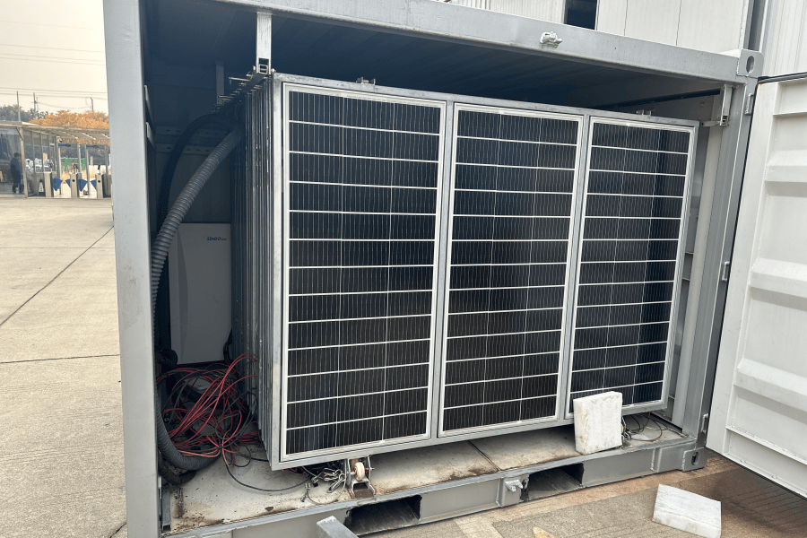
This is where the "pre-integrated container" model changes the game. At Highjoule, when we talk pre-integrated, we mean the entire ecosystem - battery racks, grid-forming inverters, thermal management, fire suppression, and step-up transformers - is factory-assembled, wired, and tested in a single, UL-certified enclosure. Think of it like buying a fully equipped, inspected kitchen instead of a pile of lumber and appliances.
The benefit for your step-by-step installation is massive. It shifts 80% of the complex electrical work from your windy, rainy, time-pressured site to our controlled factory floor. We run what we call a "megawatt-scale burn-in test" on every unit, simulating real load profiles. This means by the time it's on the truck, we know it works. Your risk shifts from "will this system function?" to "is my site ready to receive it?" C a much simpler question to answer.
The Installation Blueprint: A Step-by-Step Field Guide
Based on our deployments from Texas to North Rhine-Westphalia, here's the streamlined process a good pre-integrated system enables:
Phase 1: Pre-Site Delivery (The Most Critical Phase)
Site Assessment & Foundation: This isn't just a concrete pad. We need a level, reinforced foundation that accounts for both the static weight and the vibrational forces from the transformers inside. We provide the exact civil drawings. Get this wrong, and you're jackhammering on Day 1.
Utility Interconnection & Permitting: This is where our local engineering partners earn their keep. We jointly handle the interconnection studies (like the IEEE 1547-2018 compliance for grid-forming) and package all the UL 9540, IEC 62443 system certification docs for the AHJ (Authority Having Jurisdiction). Having these pre-approved packs cuts permit review time by weeks.
Phase 2: Delivery & Placement
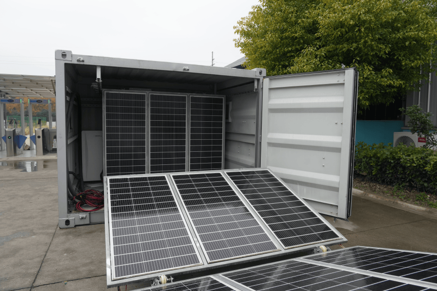
The container arrives on a specialized trailer. With a 500-ton crane, placement is usually a half-day operation. The key is clear access and having that foundation perfectly located. I remember a project in an Austrian alpine town where we had to coordinate with the local train schedule for road access C planning is everything.
Phase 3: The "One-Connection" Hookup
This is the beauty part. Instead of hundreds of field terminations, you have essentially three main connections:
- AC Power In/Out: A single, large-diameter cable to your main switchgear or EV charging power distribution unit.
- DC Solar Input: Pre-sized conduits for the PV string cables from your carport or ground-mount array.
- Communications & Control: A single ethernet/fiber link to your energy management system (EMS) for monitoring and dispatch.
The grid-forming inverter is already synced with the battery management system (BMS) inside. You're not connecting components; you're connecting a fully functional power plant.
Phase 4: Commissioning & Grid Sync
Our field engineer boots up the system, runs a final functional test, and initiates the first grid synchronization. The grid-forming inverter's job is to establish stable voltage and frequency from a black start - it essentially tells the grid "I'm here, and I'm stable," rather than asking the grid for permission. This is the magic moment. We then train your onsite staff on the basic HMI for daily checks.
Beyond the Basics: The Expert Insights That Matter
Let's get technical for a minute, in plain English. When evaluating a container for EV charging, don't just look at the megawatt-hour (MWh) rating.
- C-rate is King for Charging: A high C-rate (like 1C or above) means the battery can discharge its entire capacity in an hour. For a 1 MWh system, that's 1 MW of power. For EV fast charging, you need that burst power. A low C-rate battery (e.g., 0.25C) is cheaper but can't deliver the punch for multiple fast chargers, defeating the purpose.
- Thermal Management = Longevity: In a sealed container in Arizona or Spain, heat is the enemy. A passive cooling system might not cut it. Look for a liquid-cooled, HVAC-climate-controlled environment. It keeps cells at optimal temperature, extending cycle life and maintaining safety. This directly lowers your Levelized Cost of Energy (LCOE) - the total lifetime cost per kWh - for the system.
- The Grid-Forming Brain: Ensure the inverter's grid-forming logic is certified to the latest standards (like UL 1741-SB). It should provide synthetic inertia and black start capability autonomously, not as an add-on feature.
Your Next Step: Asking the Right Questions
So, when you're talking to vendors, move beyond the spec sheet. Ask them: "Walk me through your step-by-step installation process for a site with [your specific grid voltage]." Ask: "Can I see the factory integration and test report for a recent project?" Ask: "How does your grid-forming control handle a sudden loss of the main grid while my chargers are at full load?"
The right partner won't just sell you a container. They'll provide the blueprint, the local compliance muscle, and the decades of field experience that turns a complex installation into a predictable, successful project. That's how you build an EV charging hub that's not just a cost center, but a resilient, revenue-generating asset for the next 20 years.
What's the biggest hurdle you're anticipating in your next EV infrastructure project?
Tags: UL Standard BESS LCOE Europe US Market EV Charging Infrastructure Renewable Energy Pre-integrated Container Grid-Forming Inverter
Author
James Zhang
20+ years agricultural energy storage engineer / Highjoule CTO